AIR FLOW SCHEMATICS
|
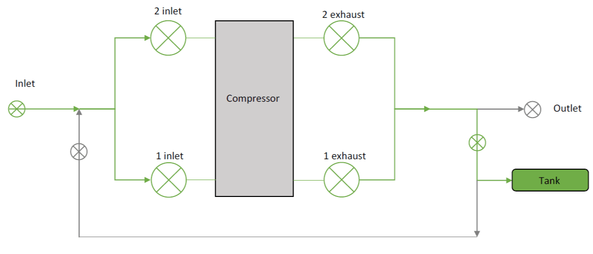
The schematic on the left shows the state of the electrically controlled valves during compression (braking). In this schematic, green valves indicate open valves and grey ones are closed. The intention of this setup is to force all the air into the storage tank while the rickshaw is braking. The compressor is driven off of the rickshaw rear drive axle.
|
|
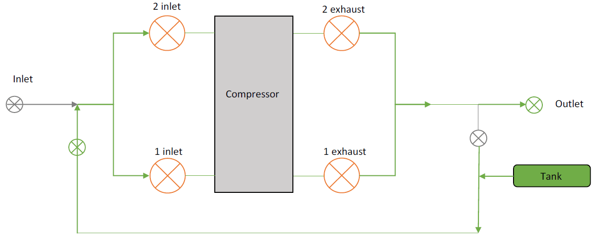
The schematic on the right shows the state of the electrically controlled valves during acceleration of the rickshaw. In this schematic, green valves indicate open valves and grey ones are closed. Red valves are electrically controlled and are opened and closed according to the rotational speed of the compressor shaft. The intention of this setup is to utilize the stored air from the tank to spin the compressor shaft and thus, accelerate the rickshaw.
|
|
ELECTRICAL SCHEMATICS
|
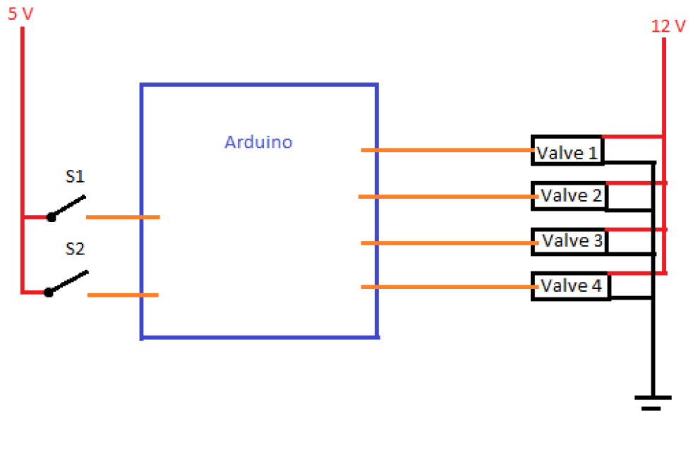
The electrical control system of the valves that is activated during acceleration is shown on the left. S1 and S2 denote switches 1 and 2 respectively. These switches open and close according to the positions of the pistons in each cylinder. Since the rotation of the two pistons is 180 degrees out of phase, the switches were positioned on the compressor shaft with 180 degrees of separation. The switch implementation is shown in the image below. Note that this diagram is simplified and omits the power transistors used to control the valves.
|
|
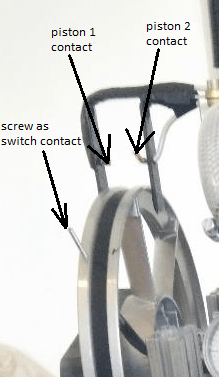
This image shows how the switching mechanism was attached to the compressor. Two screws at 180 degrees of separation were screwed into the compressor's rotating pulley wheel. The entire compressor was grounded electrically and so both screws were held at ground voltage. Piston 1 and 2 contacts were both held at 5 volts and so as the compressor shaft rotated, alternating switches were opened and closed. During compression, when the inlet valve of one cylinder was opened, the outlet valve of that cylinder was closed. The opposite would be done in the other cylinder. During acceleration, all four valves were open regardles of the shaft position.
|
|
|
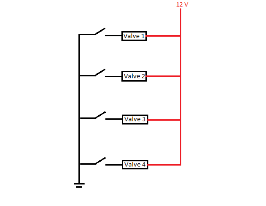
The electrical control system of the valves that is activated during compression (braking) is shown on the right. During compression all of the valves were held open. Therefore, the the circuit on the right could be simplified to contain only one switch but independent switches were kept in order to easily diagnose issues with particular valves. The switches took the form of single pole toggle wall switches.
|
