COMPRESSOR MODIFICATION
|
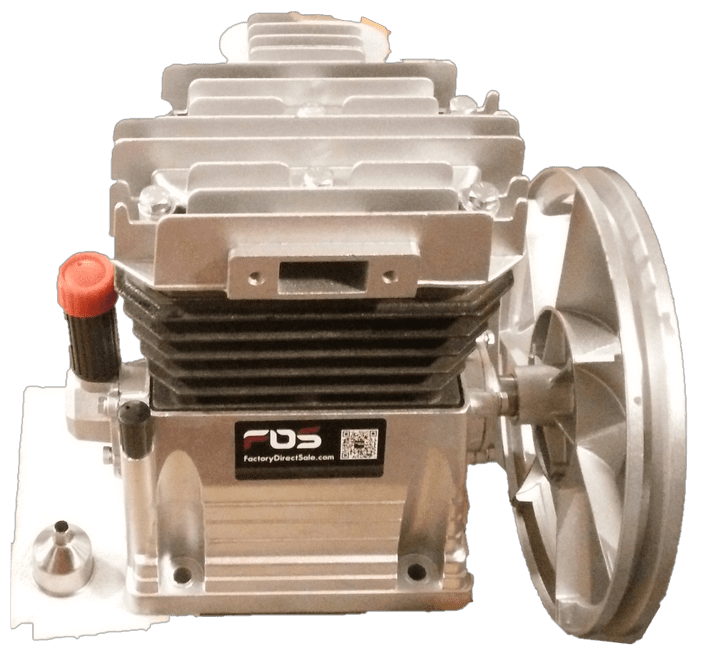
At the core of the pneumatic regenerative braking system is a 2-cylinder reciprocating compressor. Internal components and modifications made to the compressor are shown below.
|
|
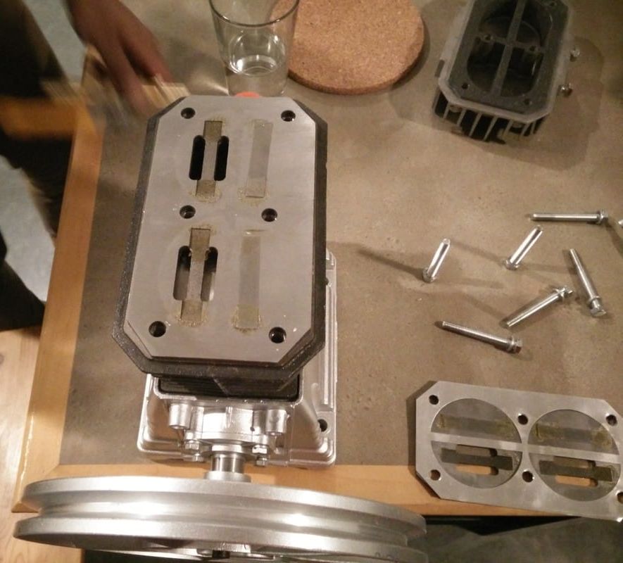
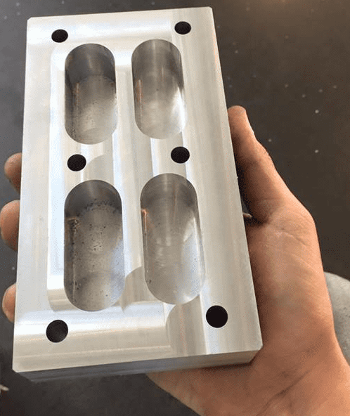
Top View of Compressor (Head Removed)
The flat metal strips which can be seen on the head block as well as the gasket piece on the right are simple one way valves. These valves allow air to only flow either in or out of their respective cylinder. In the top right corner, the original compressor head can be seen and it is shown in more detail in the image below. |
|
|
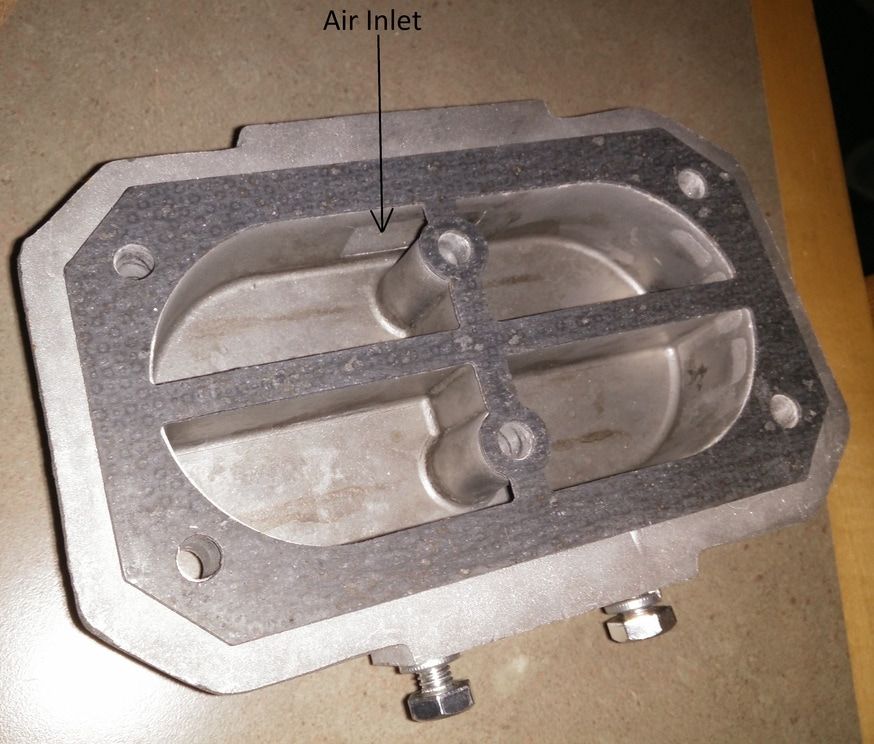
The original compressor head block is shown in detail here. Looking closely at the wall, it can be seen that the air inlet is shared between both the right and left cutouts. The same is true for the air outlet which is on the exact opposite side of the inlet. This meant that both cylinders in the compressor shared a common pressure at all times.
However, in order to use a compressor as an engine it was necessary to modify the compressor head so that both cylinders were independent of each other. This meant that each cylinder needed to have its own inlet and its own outlet, as is the case in a typical engine. |
|
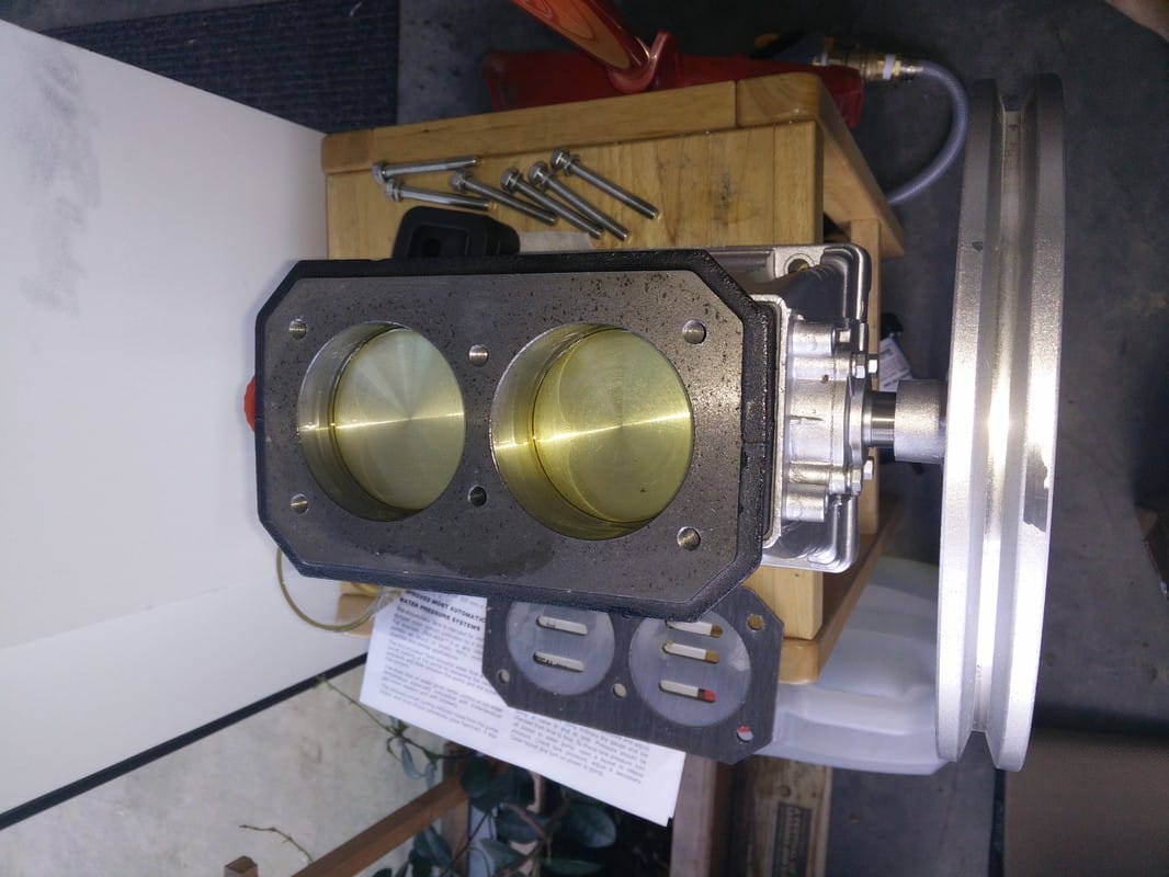
Top view of compressor with cylinders and piston heads exposed.
|
|
|
As explained earlier, each cylinder needed to have its own inlet and outlet, which could be indepently opened and closed. This required each cylinder to have 2 independent chambers in the head block.
The piece on the left is a machined aluminum block which has 4 independent chambers. In the wall of each chamber, a hole was machined in order to install electrically controlled solenoid valves. |
|
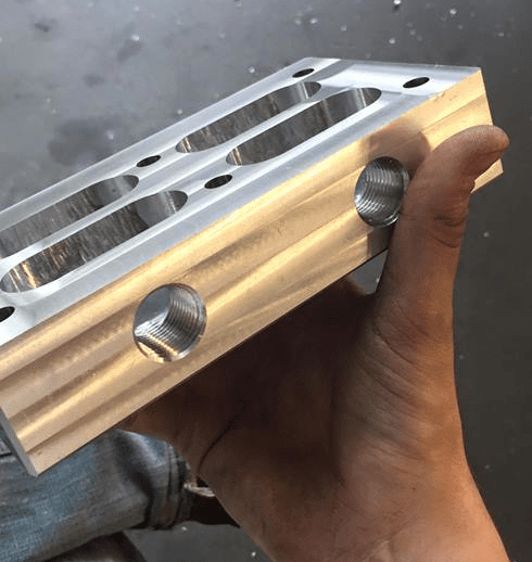
This is the completed head block with threaded holes for installing electrically controlled valves on all inlets and outlets.
|
|
FRAME CONSTRUCTION
|
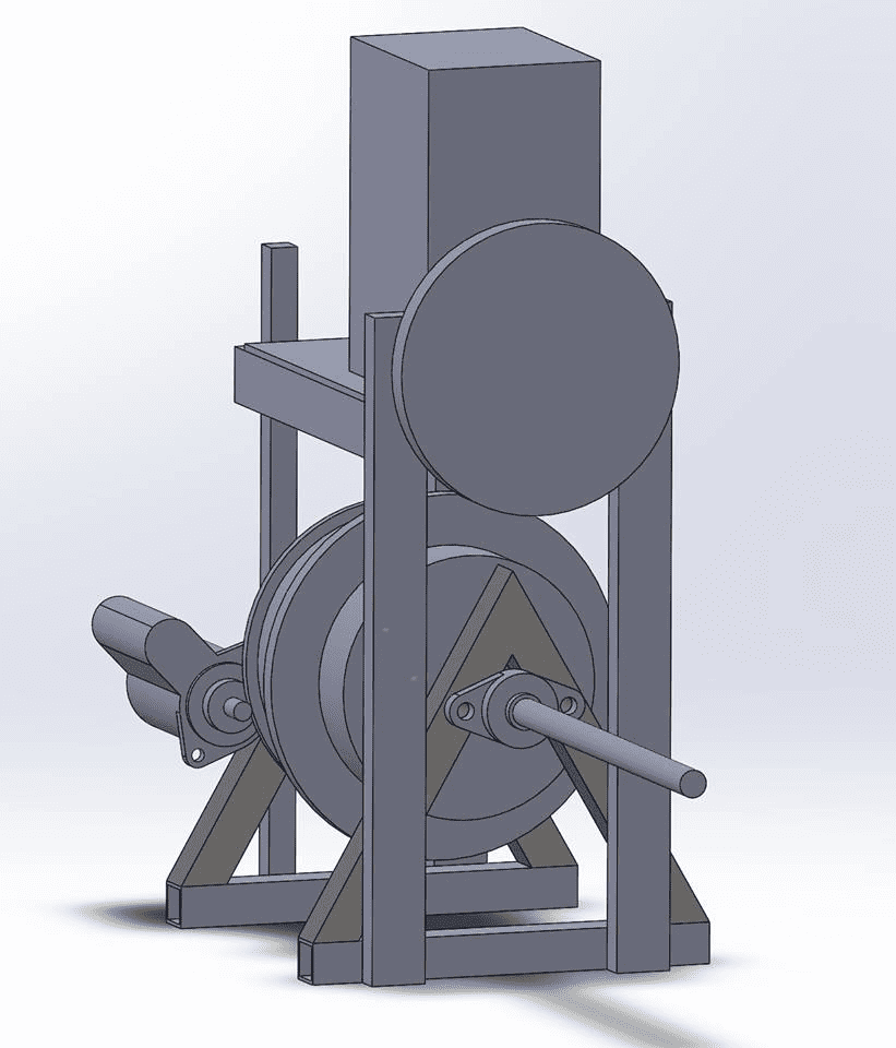
CAD model of final prototype that was used for proof of concept and demonstration purposes.
|
|
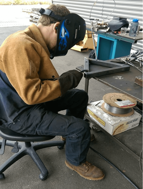
Construction of base frame from hollow square steel tube.
|
|
|
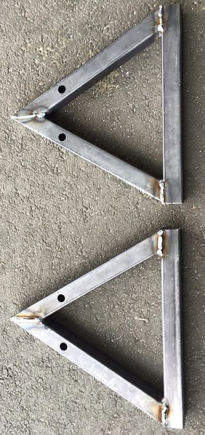
Finished base frame pieces.
|
|
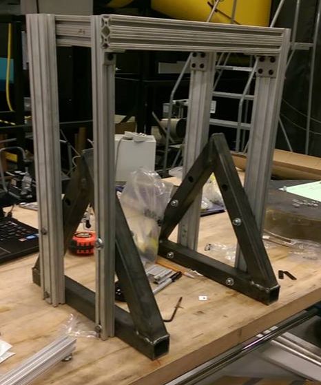
Assembled support frame using base pieces and aluminum extrusion bars.
|
|
COMPLETED PROTOTYPE
|
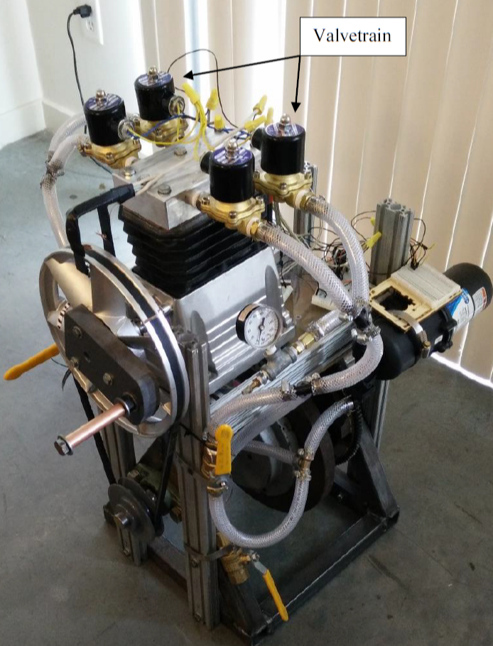
Isometric view of completed prototype.
|
|
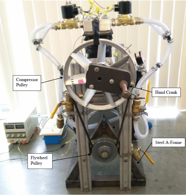
Front view of completed prototype.
|
|
|
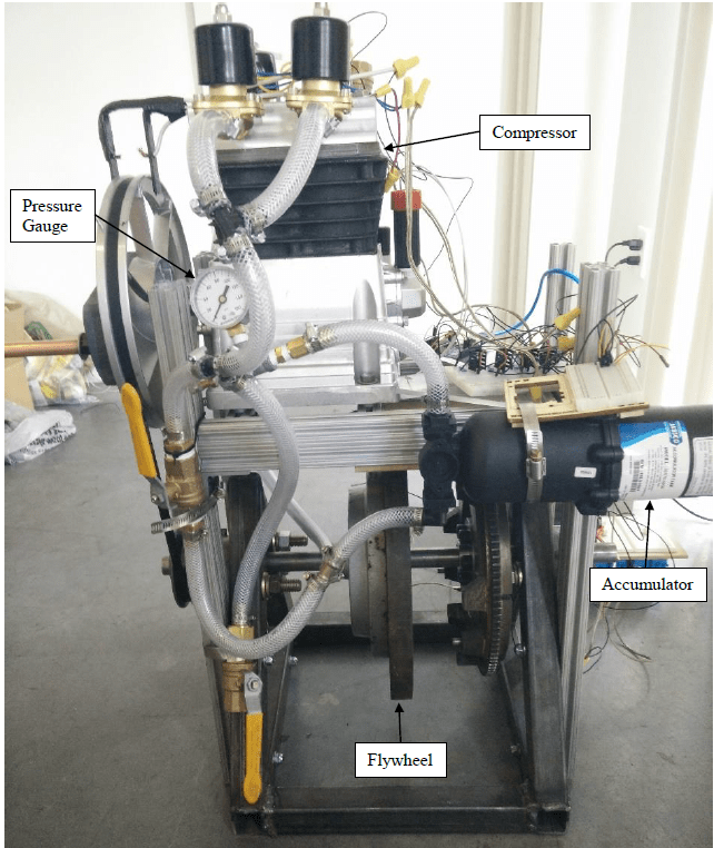
Side view of completed prototype.
|
